Update: Part 2 can be found Here:
Part 2: CAD and Machining
I thought since I'm now locked down because of the coronavirus that I would start a new project. I was quite fascinated with the cubli, it's amazing how well tuned it is, but the part that impressed me the most was how quickly it rejected disturbances and re-stabilized. Over the last few weeks I've gotten started, and I've gotten a good amount done, but this will be done in parts as it will be quite a long project.
The Motor
I thought I would start with the motor, since without that I couldn't really design much of anything outside of the Accelerometer/Gyro. This would probably be significantly easier with brushed motors, but I want to avoid that for a couple of reasons. First, the kind of brushed motors that I would need are very expensive because of the rare earth magnets used in them, and secondly, I think it would be cool to try building my own encoder for a brushless motor.
The Encoder
This is the first big hurdle in the project. Most (cheap) commercial ESC's use back EMF to determine the position of a brushless motor. That won't work here because I'm going to need to be able to drive the motor at slow speeds (you can't easily do this with backEMF because the slower a brushless motor goes the more current it takes to drive, making it very hard to detect the back EMF). I also need to reverse, which is a problem with back EMF because you obviously have to go slow before you reverse. For these reasons I went with Hall Sensors. They should detect the position of the rotor regardless of its speed, position, or direction, but they will be quite a bit harder to set up.
Design iterations
I created many different Hall boards before I settled on a final design, below are a few iterations:
Hallboard 1:
hand drilled pcb meant that hall sensor position was not accurate. They were not easy to space 60 degrees apart, and were not equidistant from the motor. Hand positioning with an oscilloscope was tedius and results were still not very reliable. Used A3144 through hole hall sensors, which were not as sensitive as I was hoping.
Hallboard 2:
Significantly better than hallboard one, professionally fabricated PCB fixed the hole placement issue. Switching to new, more sensitive hall sensors (A1302) made results more reliable, however their placement along the outside of the motor meant that the magnetic field was still too weak to get reliable readings. The quiescent voltage of the sensors was 2.5V, and I observed readings from 2.1-2.65 volts depending on magnet polarity. I used external comparators to create a digital signal for the arduino, but I was worried that motor steps would be skipped because hall sensors would not detect the field.
Hallboard 3:
Far better than the other two. I switched to SMD hall sensors after the position had been fine tuned, which made placement almost impossible to screw up. The Hall sensors were moved to the poles of the magnets where the field is stronger, as opposed to the outside of the motor. I switched to the newer A1304 sensors which seem to be much more sensitive as well, the quiescent voltage is 1.65v, and I observe a range from 0.1 volts to 3.2 volts, a much more comfortable range. I removed the comparators with the intention of using the Teensy's internal comparator (with the quiescent voltage on the AREF pin), however it works so well as is that I don't think that's necessary.
Testing on the oscilloscope
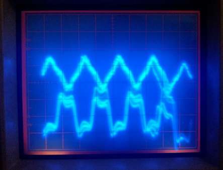
Before I ran the motor, I used a different motor to spin it up, with the oscilloscope connected to two of its phases. By using a different motor to spin the first, you can view nothing but the back EMF, which is much easier than just using one motor.
Here is an example of the output of middle hall sensor (hall sensor on bottom, EMF on top). The middle one should be inverted in a 12N14P motor, meaning low back EMF should correspond to high on the sensor.
Heres a picture of what that looks like:
After that, I used the following code just to verify that it was all working nicely, this is the output as I rotate the motor by hand.
// If 1, states will be output numerically, ie. 3 instead of 011
#define NUMERICAL_STATES 0

//define hall Sensor pins
const short HA = 2;
const short HB = 3;
const short HC = 4;

short state = -1;
void setup() {
  Serial.begin(115200);

  // The A1304 output pin must be pulled up to 3.3v
  pinMode(HA, INPUT_PULLUP);
  pinMode(HB, INPUT_PULLUP);
  pinMode(HC, INPUT_PULLUP);
  pinMode(13, OUTPUT);

  delay(1000);
  // turn on the on-board LED to indicate logging has started.
  digitalWrite(13, HIGH);
}

// Get the current state of the hall sensors.
// if the state has changed we must commutate windings.
void loop() {
  int new_state = GetHallState();
  if (state != new_state) {
    if (NUMERICAL_STATES)
      Serial.println(new_state);
    state = new_state;
  }
}

// Returns the current position of the rotor.
// -1 should not be possible, if hall sensors don't match the 6 steps E-Stop.
short GetHallState() {
  int hallA = digitalRead(HA);
  int hallB = digitalRead(HB);
  int hallC = digitalRead(HC);

  if (!NUMERICAL_STATES) {
    Serial.print(hallA);
    Serial.print(hallB);
    Serial.println(hallC);
  }
  // Converts hall sensor readings to numerical states
  // 101 001 011 010 110 100
  if (hallA && !hallB && hallC)
    return 1;
  else if (!hallA && !hallB && hallC)
    return 2;
  else if (!hallA && hallB && hallC)
    return 3;
  else if (!hallA && hallB && !hallC)
    return 4;
  else if (hallA && hallB && !hallC)
    return 5;
  else if (hallA &&  !hallB && !hallC)
    return 6;
  else {
    // This should never happen, if it somehow does, states of the hall sensors are
    // printed at the time of failure for debugging purposes. This also calls
    // the emergency stop in the full program.
    Serial.print(hallA);
    Serial.print(hallB);
    Serial.println(hallC);
  }
}
This was harder than I expected to set up, so I figured I'd go through the problems I had in case anyone is doing something similar.
- I started this by milling PCBs on a CNC machine, but using through hole components meant that I couldn't exactly align the hall sensors every time. This offset caused my controller to switch magnets at (slightly) incorrect times, leading to a huge increase in heat as well as increased current draw. This was fixed by using SMD components. Applying solder paste and reflowing all the components onto the board made a huge difference in heat and current draw.
- My power supply was insufficient. I have a 30V 5A max variable power supply that I was testing on, however I noticed the power to the microcontroller was dipping significantly when the motor was running slower. This led to the microcontroller browning out and outputting insufficient voltage to the gates, only partially opening the MOSFETS and causing one to heat up very quickly and explode. This was fixed by testing on a LIPO battery, which has much higher burst currents and allows me to slow the motor much more without excess heat.
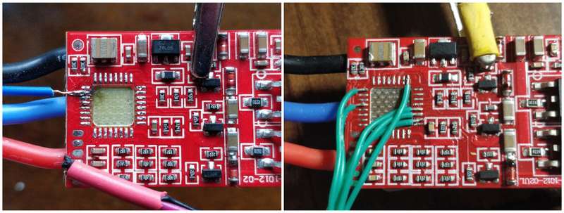
- To test, I simply de-soldered the Atmega8a chip on the ESC and soldered my own wires to the pins that controlled the MOSFETS (more on this later). This allowed me to control the motor without building my own ESC, but it is not very clean. I may attempt to build my own ESC for this later on. The advantage of this however is that if it does not work, you know that the problem is with your setup, and not the ESC itself.
The ESC
As I said earlier, I used a multimeter to determine which pins of the Atmega8a were controlling the MOSFETS, and soldered my own wires to them to control the ESC externally. This is what that setup looks like:
This was my first attempt soldering on something this small, the wire was too long and I had a hard time getting a clean joint, so you can see scorch marks on the board. Here's the fully wired up ESC:
The ESC also has an UBEC which I am using to power the arduino, however I am going to change this because I don't want the same thing to happen to the MOSFETs if the power through the UBEC drops again.
State of the project
Currently, I am able to control the speed of the motor. I can make it go slow, fast, and in reverse. This is a significant part of the project so hopefully I'll be able to get working on some code soon.
For now, this is the roadmap for the project:
Future
- Machine the Flywheel, Faceplate and Mounts
- Simulate the Initial "pop-up" of the Cube
- Add Accelerometers/Gyroscopes
- Software, PID/Kalman Filter
Completed
- Design and Fab Hall Sensor Board
- Control the ESC from the Teensy 3.5
With the Motor and Encoder working, it's time to design the body of the cube
Part 2: CAD and Machining


