The CAD files for all the parts of this robot are available on my Github Here.
Design
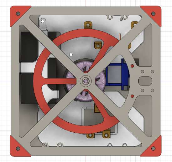
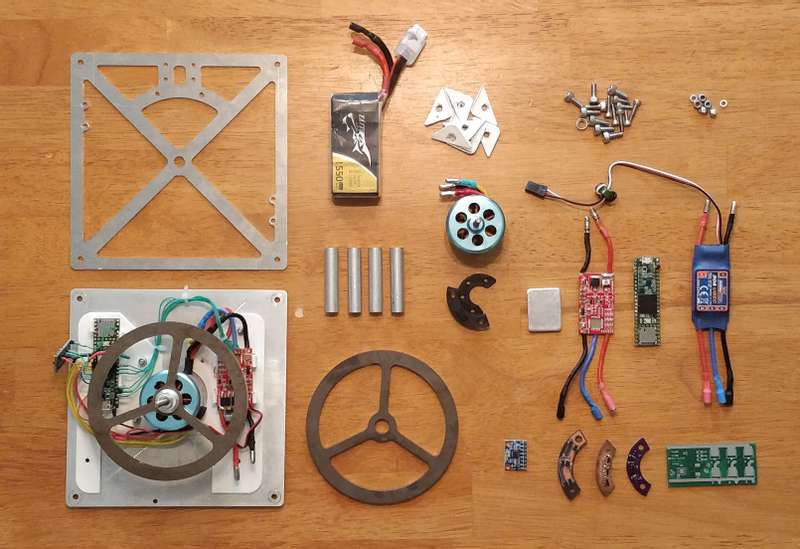
I started with a simple Backplate design with holes to attach a 3d printed mounting plate for the PCBs. The reason I did this was because it's faster and cheaper to just print a new mounting plate rather than machine a whole new metal Backplate every time I make a change to the layout of the electronics. The final PCB mounting plate will be machined out of lexan. The backplate is relatively heavy, but the motor should easily produce enough torque to flip the cube anyway.
I made standoffs out of some 3/8" aluminum rod on my drill press, and faced them flat with the CNC. They're not machined (beyond facing) but they are all cut to 45mm, the height of the motor plus the flywheel and its clamp with an offset of 1mm.
The Faceplate only has to mount the accelerometer/gyro, so there are a lot less mounting holes. It has a 7.5 mm hole in the middle to retain a 7.5mm OD 4mm ID flange bearing that fits on the shaft of the motor. I was concerned at the time about how well balanced the flywheel would be, so the bearing is there to share some of the lateral load and keep stress off the motor mount. After testing the motor with the faceplate off there is no visible wobble anyway, but its nice to have extra rigidity. In case the cube didn't have the power to flip, the backplate also has a mount for a servo motor that would push a brake against the flywheel. This was unnecessary, but I left it because it would be fun to experiment with that in the future.
The face and backplates are both 150mmx150mm for not much reason other than that the original was the same dimensions. The flywheel is made of 304 steel and weighs 142 grams, the added weight helps the spinning flywheel store more energy.
Code Update:
I've finished the trajectory prediction now, after the code is cleaned up it will be on Github with the rest of the cube files. I am also doing a writeup now that will be available from this page soon.

