One of the things I love to do when I find a project that interests me is to try to recreate it myself without viewing their code/cad files etc. Because the purpose of my projects is to learn, I am sure many of the things I post could be done more efficiently. If you have any ideas, I'm always open to suggestions (:
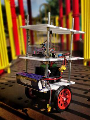
Below is the current iteration of my robot:
The Hardware
I started with the obvious hardware, I needed motors, motor drivers, and something to power them. I decided to go with the arduino due as the main microcontroller as it's quite fast, and the SAM chip allows more external interrupts than other arduinos. I also needed an accelerometer/gyro to create a simple feedback loop.
Heres what I went with:
2x NEMA 32 2.8A 1.9NM Stepper motors (I went with stronger 1.9NM motors so I could build on the robot later without having to worry about power.)
2x SainSmart ST-M5045 Stepper Drivers
1x MPU9050 Accel/gyro
1x 24v to 12v step down converter
The Frame
After I had all the electronics, I needed to build a frame for the robot. I went with a large sheet of HDPE that I cut down to size on my table saw, and some cheap threaded rod.
I cut the threaded rod down to size with a dremel, drilled holes in the HDPE to thread the rod through, and held everything in place with nuts and locking washers. I also drilled a hole to feed the motor wires through, and put in a grommet to protect the wires from fraying and shorting. Then, I simply had to mount all the electronics, and I could begin working on the code.
The Code
The full current code can be found on my Github page here. I'll just give a brief discription of what each of the files does here, there were too many changes and problems and fixes to do a full write up of the process:
mpu.cpp:
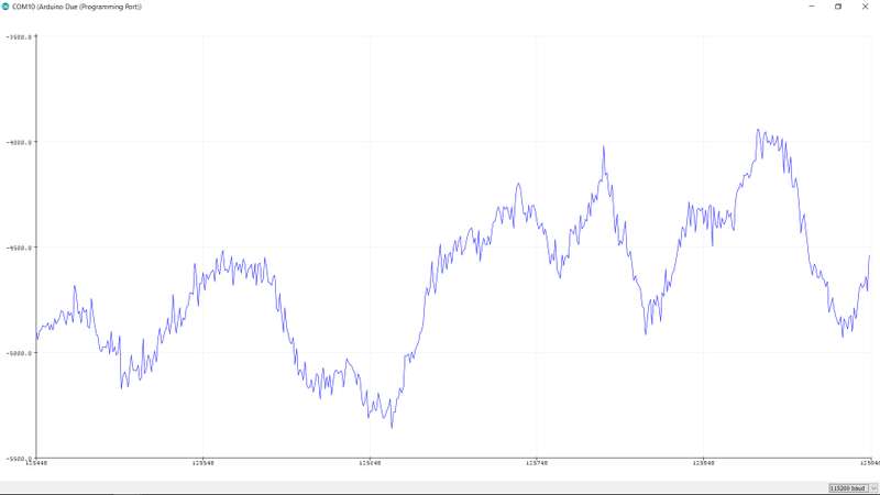
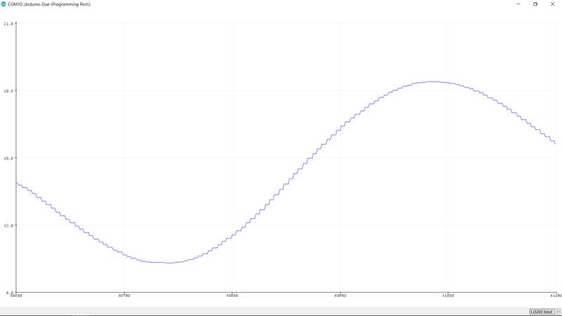
My first approach was to read the raw data from the accelerometer, and run it through a kalman filter to remove as much noise as posssible. This kind of worked, but was very volitile, and the robot would eventually experience a "spike" in values that caused it to accelerate very quickly and fall over. Later I learned that the mpu itself could filter the data via its on-board dmp (digital motion processor). This provided a much smoother output that made the robot a lot more stable. Below you can see the raw output of the accelerometer vs the filtered output of the DMP:
Here I simply read the quaternion values from the dmp, convert to degrees, and put them into a FIFO buffer to be fed into the PID controller.
NMBot.cpp
This file handles almost all the calculations done by the robot. It receives values from the mpu, feeds them into the PID controller, and maps them to a speed that can be outputted by the motor. Here is a graph of the PID controller [IMAGE]. red is the setpoint, blue is the pid output, and green is the PID's input directly from the mpu.
Timers are done differently on the Due than other arduino boards, I used the SAM#X8E's wave generator to trigger an interrupt at the frequency we want. We pass it an IRQ channel and choose the TC handler function that will be called on the interrupt.
void NMbot::startTimer(Tc *tc, uint32_t channel, IRQn_Type irq, uint32_t frequency) {
    pmc_set_writeprotect(false); //allow writing to timer registers
    pmc_enable_periph_clk((uint32_t)irq); // Enable clock for the timer
    TC_Configure(tc, channel, TC_CMR_WAVE | TC_CMR_WAVSEL_UP_RC | TC_CMR_TCCLKS_TIMER_CLOCK4); //configure timer in waveform mode
    uint32_t rc = VARIANT_MCK / 128 / frequency; //128 because we selected TIMER_CLOCK4 above
    TC_SetRA(tc, channel, rc / 2); //50% high, 50% low
    TC_SetRC(tc, channel, rc);
    TC_Start(tc, channel);
    tc->TC_CHANNEL[channel].TC_IER = TC_IER_CPCS;
    tc->TC_CHANNEL[channel].TC_IDR = ~TC_IER_CPCS;
    NVIC_EnableIRQ(irq);
}
NMRobot.ino
This is the "main" file where everything is set up and called. It's also the file that actually receives the callback from the tc handlers and turns the motors. PullLeft (boolean) flips every time the function is called, and passed into digitalWrite it resolves to an integer:
void TC3_Handler(){
    TC_GetStatus(TC1,0);

    pullLeft = !pullLeft;
    digitalWrite(PUL_PIN_L, pullLeft);
}
Problems
Gyroscopic Drift:
As it turns out, the pitch axis on my gyroscope drifts over time. This happens with all gyroscopes, but the drift was so strong that the robot would eventually drive itself into the ground. I fixed this by switching to the roll axis, which drifts a negligible amount.
Axle Material:
The axles were orignally 3D printed in PLA plastic. I knew over time that they would wear down and need to be replaced, so they were printed simply as a placeholder so I could do some testing. Unfortunately, I underestimated the torque the motors could produce, and one of them shattered. I'll fix this in the future by milling some aluminum axles to fit in their place, with grub screws to keep them tight.
Weight:
This problem remains unsolved. At the moment the robot can stabilize itself, but only at +- 5 degrees from 90. If it falls higher or lower, the motors cannot accelerate fast enough to keep it stable. There are a few solutions to this: Bigger motors, more power, less weight, and bigger wheels. So far I have lowered the platforms to reduce lower the center of gravity, and I hope to try again with the bigger wheels soon, this should fix the problem.
Ongoing
This projects is not complete. I am a full time student at the University of Houston, and since school has started up I have not been able to work on this project as much. Hopefully I'll be able to move forward on it sometime during the christmas break. My next step will be to design new mounts for the larger wheels, and see what happens from there.


